Description
Variable Pattern Microphones
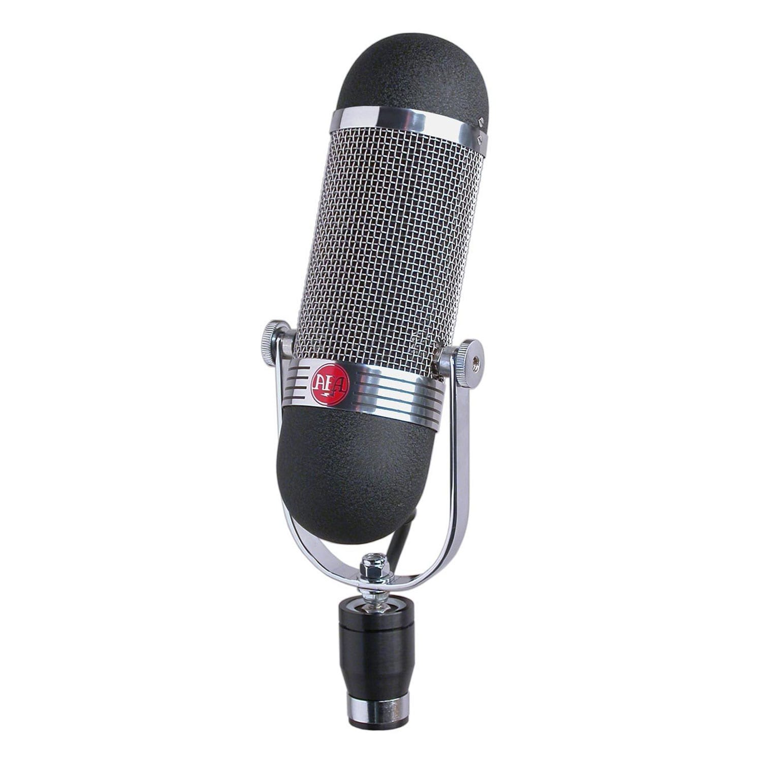
Series Seven microphones provide unprecedented flexibility, as the directional pattern of the mic can be adjusted in use, during, or after recording. C700 microphones include omni/pressure and figure-8/gradient capsules, each with a discrete output. The signals can be recorded on separate tracks, so the pattern can be selected in the mixdown. Pattern control is only one advantage of this technique.
Applying different equalization or dynamic control to the capsule signals makes entirely different mic characteristics – for instance, the warmth of a gradient mic used close up for vocal might be combined with the transparency of a pressure mic in the highs, by rolling off the high frequencies in the gradient signal and the lows in the pressure signal before they are combined.
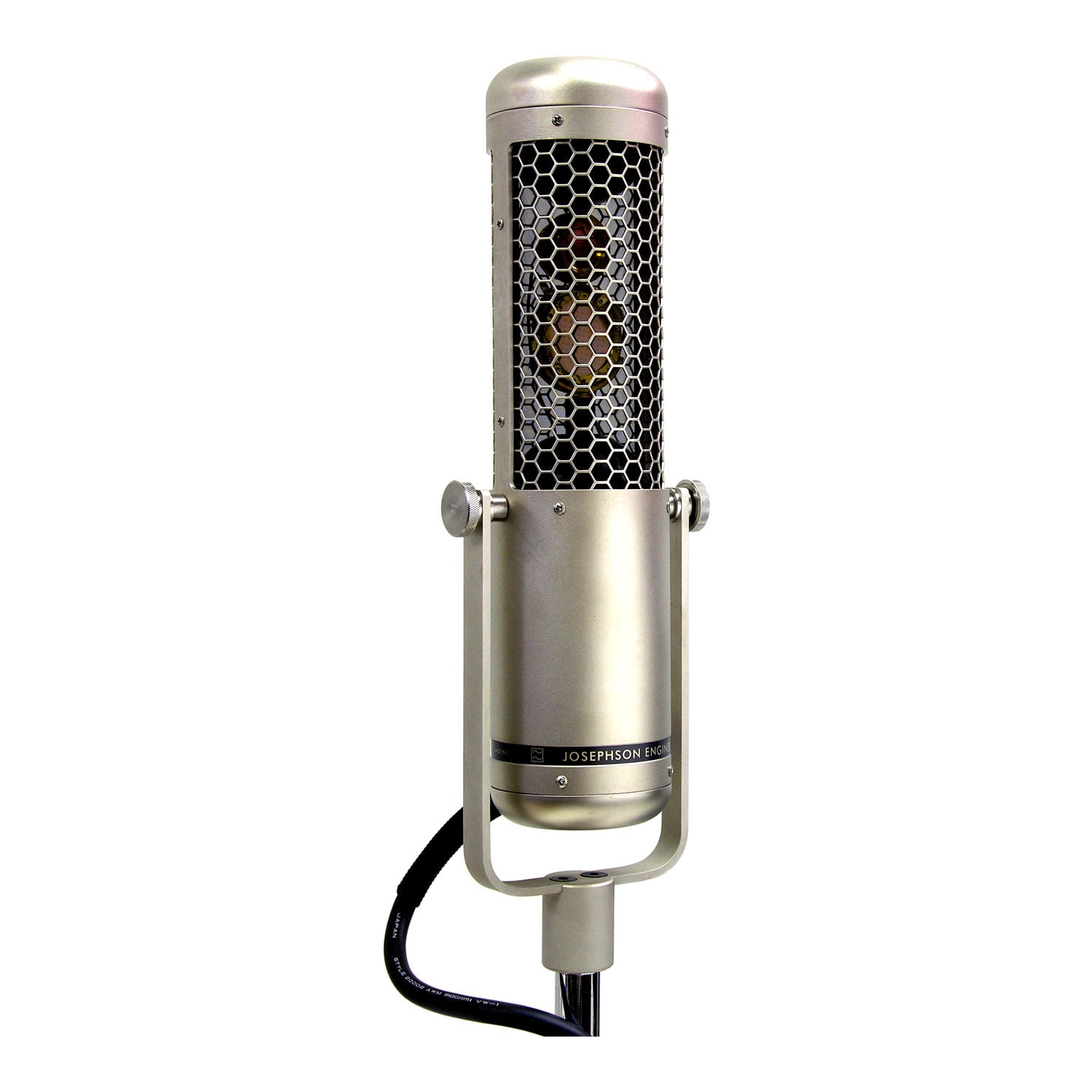
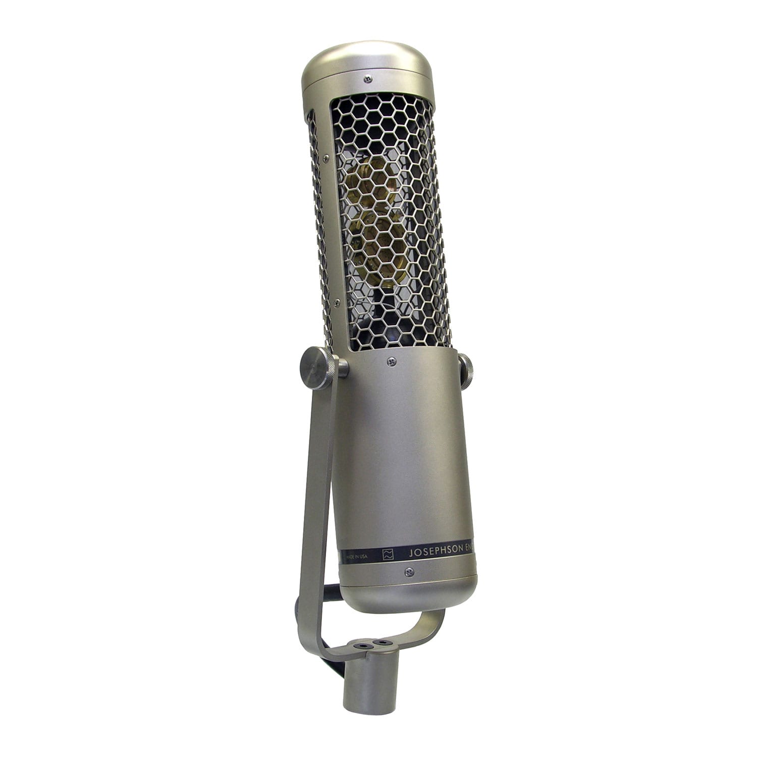
The Josephson Engineering C700A includes two capsules in one housing, a 16mm omni element similar to the KA11 capsule in the Series Six, and a 26mm figure-8 capsule. Completely neutral electronics, using the same cascade FET input, class-A active balanced output circuit found in Series Six, are provided for each signal. Any directional pattern from omni to figure-8 may be selected by controlling the ratio of pressure to gradient signals.
The C700S microphone has three capsules; an additional side-facing figure-8 capsule is added to the two in the C700A. Any coincident stereo pickup can be derived from mixing these three signals together, and like the C700A, the signals can be recorded individually and all aspects of image width and pattern control may be adjusted in the mixdown. With the three capsule signals, any number of microphone outputs may be created, each one pointed anywhere in the plane around the microphone.
The capsule assembly in the Series Seven is internally shock mounted, so that the mic may be attached directly to a stand through its yoke mount without any external accessories.
Using the C700A and C700S
The outputs of the C700A microphone are designated W for omni/pressure, X for front-facing figure-8/gradient; the C700S also has a Y output for side-facing figure-8/gradient. These native output signals from the microphone are equivalent to Soundfield “B-format” except that the height or “Z” channel is absent. Any desired pattern can be obtained by mixing these signals, and with the C700S the resultant output may be pointed in any direction. Any number of output channels may be derived by mixing additional copies of W, X, and Y in different ratios.
Pattern selection (C700A and S)
Omni: all W
Subcardioid/hypocardioid: W with X mixed in about –6 dB
Cardioid: equal amounts of W and X
Supercardioid/hypercardioid: X with W mixed in about –6 dB
Figure 8: all X
To reverse direction (unidirectional patterns favoring the rear of the mic) invert the phase of the X signal
MS Stereo (C700S)
The M or mid signal is formed by mixing W and X. If the signals are at the same level, a cardioid pattern will result. The Y signal is equivalent to the S or side signal in MS Stereo.
XY Stereo (C700S)
MS can be converted to left/right using the usual matrix, M+S=left, M-S=right. On a mixer, this is accomplished by connecting the W and X signals to mixer inputs panned center. A Y-cord is needed to split the output of the Y channel into two more mixer inputs. The first of these is panned left, and the second is phase inverted and panned right. The pattern is adjusted by controlling the ratio of W and X; raising the level of the Y and inverted-Y signals panned left and right controls the width.
Surround formats (C700S)
The five primary surround channels can be derived using the XY stereo recipe above for the front and making a duplicate set (with the X signal inverted) for the rear.
Left front: W+X+Y
Center front: W+X
Right front: W+X-Y
Left rear: W-X+Y
Right rear: W-X-Y
The W signal has a flat response to below 20 Hz and can be used alone, with suitable lowpass filtering, as the 0.1 or LFE channel. Side-facing channels may be derived using the W and Y signals just as forward-facing channels are made with W and X.
Specifications common to C700 series
– Pressure and pressure gradient condenser microphone transducers
– Variable directional pattern achieved by mixing output signals (see over)
– Frequency range 20-20,000 Hz ±2 dB from the reference curve
– Sensitivity –41 dB ref 1 V/Pa (9 mV/Pa) for each signal
– Overload sound pressure 135 dB SPL at 1kΩ load for <1% THD
– Equivalent noise level 15 dB SPL, A-weighted
– Power supply P48 phantom, 4 mA per output
– Diameter 63mm (100 mm wide at yoke), length 328 mm (C700A), 365 mm (C700S)
– Output connector 5-pin XLR type (C700A), 7-pin XLR type (C700S)
