Description
Clean, precise, powerFUL level control.
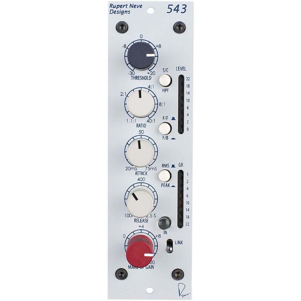
Whether you’re tracking, mixing, or mastering, the 543 delivers unobtrusive, musical dynamic control and high-ratio limiting with massive flexibility, transparency, and precision.
The 543 features a fully controllable compressor-limiter with feed-forward / feedback modes, Peak / RMS detection, and a built-in side chain high pass filter. With an unrivaled heritage and a tremendous feature set, the 543 provides an astonishing degree of flexibility and precision.
What is VCA compression?
Every compressor has a gain control element in its circuit, and this is generally what determines the “sound” of the compressor. Some compressors use tubes, some use FETs, some use light-dependent resistors, and some use a diode bridge – but in the 543, a VCA (Voltage Controlled Amplifier / Attenuator) is used to control the signal’s gain.
In contrast to a diode bridge design like our 535 compressor, which adds a thick, very colorful tonality to the source, the 543 makes use of a very accurate, low noise, low distortion VCA. This provides an immense amount of dynamic control and subtle warmth, without necessarily leaving a heavy sonic imprint on your tracks or mixes.
Feed-Forward or Feed-Back?
The 543 also has the ability to switch between feed-forward and feed-back modes. If the V.C.A. Control voltage is taken from the 543 output, (i.e. after the V.C.A.) it cannot act immediately on the V.C.A. because it has already been modified by settings of the V.C.A. and circuits through which it has passed. This is known as a “Feed-Back” compressor. The two compression characteristics are quite different; there is more “Overshoot” and both the attack and recovery ramps are changed, providing the user with powerful choices.
In most of Mr. Rupert Neve’s earliest designs, feed-back detection controlling the VCA with a rectified voltage from the unit output was intrinsic to the musical dynamic response. However, the very nature of a feedback compressor limits the attack time of the compression circuit. To offer faster, more technically accurate response times, feed-forward detection was implemented on Mr. Rupert Neve’s more modern designs. With the FF / FB switch, both classic and modern VCA responses are available.
RMS or Peak?
One of the more unique features of the 543 is the new Peak / RMS mode also found in the Portico II Channel. This switch allows the VCA (voltage control amplifier) to respond to both RMS (Root Mean Square) and peak levels. RMS circuits are considered to better mimic the way the ears perceive apparent loudness, while peak circuits tend to directly respond to the waveform voltage which may be more of a concern for the prevention of clipping and maximizing levels. In this case, peak mode uses a combination of both methods to get the best of both worlds and avoids the drawbacks of each method on its own.
Ratio and Threshold
Above a given “THRESHOLD” signals are reduced by an adjustable amount ranging from 1:1, (which is linear, or no reduction at all), to more than 40:1 which is a very high ratio, equivalent to that of a Limiter. RATIO is sometimes referred to as “Slope” because when depicted on a graph, the slope of the graph representing Output versus Input, is what changes.
Ratio and Threshold are closely inter-dependent. If a RATIO as high as 40:1 has been set, then if the THRESHOLD is set at 0 dBu, even when a massive signal of +40 dBu (unlikely!) is presented to the input, the output signal will only be +1 dBu. RATIOS as high as this would normally be set somewhere above 0 dBu – say at +14 dBu, in order to prevent the output signal level from exceeding just over +14 dBu to protect, for example, a digital recorder. Similarly, if a RATIO of 5:1 has been set, an input signal which is 10dB above THRESHOLD will only rise by 2dB above that THRESHOLD at the output.
THRESHOLD control covers the Range from below -30dB to +22dBu. When THRESHOLD set at a low level, with a fairly high RATIO the amount of gain reduction will be considerable and it may be necessary to use some GAIN after the compressor to restore the apparent signal level.
Attack Time
The ATTACK time is the time taken for the compression circuits to start compressing. A long ATTACK time allows short duration peaks to “escape” and go through uncompressed. This may cause overload on subsequent digital circuits. A very short attack time sounds unnatural and robs the signal of “life” by removing transients. Some transients are extremely fast and have little effect on sound quality. Setting a long attack time often means that almost no gain reduction occurs because the transient is history (!) before compression has had time to operate. However, even the fastest circuits take time to operate which means that there is always some “Overshoot”. Small amounts of “Overshoot” are musically desirable – there are exceptions, of course.
Setting the right values of RELEASE and ATTACK is what compression is all about! Once the principles are understood a Compressor-Limiter such as the 543 provides a powerful tool that actually appears to enhance the dynamic range of a recording and so provide greater musical enjoyment.
Release / Recovery
The notes above explain how the 543 handles signals of constant amplitude such as pure tones. Real program signals, however, are continually changing in level. The way in which a compressor deals with actual program material depends upon the magnitude and duration of peaks at the program level.
If the RELEASE TIME is set to be very short, a short duration signal will be compressed but the gain will return to normal very quickly, giving a fluctuating and unnatural sound known as “Pumping” when the background, or other signals, are forced up and down. The gain will also tend to follow the waveform of low-frequency signals. RELEASE TIME should be set long enough for the gain to remain reasonably constant between each bass note or between speech syllables.
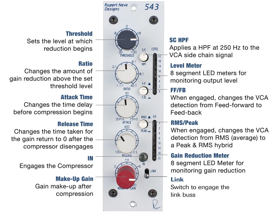
THRESHOLD
Sets level where the compressor may begin to react from -30 dB to +20 dB. Minimal or no compression is with this control fully clockwise and it gets more sensitive and tends to cause more gain reduction as the knob is rotated counter-clockwise (which may be counter-intuitive to some).
RATIO
Sets the “slope” of the compression from 1.1:1 (minimal) to 40:1 (Limit). For example, if set for 3:1 and the input signal rises by 3dB, the output signal will only rise by 1dB. In general, low ratios can not damage the music as much as high ratios but high ratios may be more useful to minimize clipping and OL lights in the recorder.
COMP IN
Engages the compressor section of the unit.
F/F + F/B
These are two very different compressor modes, FEED FORWARD and FEEDBACK. The F/B mode (button in) tends to sound smoother and often more natural and tends to be quicker to set up. The F/F mode can be more useful for shaping the envelope of the sound and introducing more bounce and pumping in time with the song when that is the goal.
GAIN
Continuously variable from -6 dB to +20 dB.
ATTACK
This sets how quickly the compressor reacts and starts attenuating. Continuously variable from 20mS to 75mS.
RELEASE
This sets how fast the compressor returns back to zero after attenuating. Typically engineers use slower release times when the intention is to minimize any obvious compressor action or gains changing. Continuously variable from 100mS to 2.5 seconds.
RMS/PEAK
This changes the compressor from essentially responding to the RMS level of the audio to also responding to the PEAK level. RMS (root mean squared) circuits are considered to better mimic the way the ears perceive apparent loudness, while Peak circuits tend to directly respond to the waveform voltage which may be more of a concern for prevention of clipping and maximizing levels.
SIDECHAIN HPF
This routes a high pass filter set to 250 Hz into the circuit that the compressor uses to determine the level. Note that the rest of the circuit and output will not have those lows filtered out – this only determines the portion of the signal that is affected by the compressor. This is very useful when you want your low-frequency content to come through unaffected while still compressing the mids and highs.
LINK
When link buss is provided by the 500 series rack, this can be used to link the reduction of two 543 units together.
SPECIFICATIONS
GAIN RANGE
Continuously variable from -6 dB to +20 dB
THRESHOLD RANGE
Continuously variable from -30 dB to +20 dB
RATIO RANGE
Continuously variable from 1.1:1 to Limit (40:1)
ATTACK RANGE
Continuously variable from 20mS to 75mS
RELEASE RANGE
Continuously variable from 100mS to 2.5 Seconds
TOTAL HARMONIC DISTORTION AND NOISE
@ 1 kHz, 0 dBu output level, no load.
Main Output, compressor bypassed: Better than 0.002%
@ 20 dBu better than 0.0015%
Main output, compressor engaged: Better than 0.075%
NOISE
Measured at Main Output, un-weighted, 22 Hz – 22 kHz, Terminated 50 Ohm.
With Gain at Unity, Compressor disengaged: Better than -98 dBu
With Gain at Unity, Compressor engaged: Better than -93 dBu
FREQUENCY RESPONSE
Main Output, Unity Gain: @ 150 kHz -3 dB
METERS
Monitors INPUT LEVEL and GAIN REDUCTION
LINE INPUT IMPEDANCE
10,000 Ohms
MAXIMUM OUTPUT LEVEL
21 dBu from 20 Hz to 40 kHz
POWER REQUIREMENTS
500 series rack with 110-125 mA @ +/- 16V


Reviews
There are no reviews yet.